Saturday 24 October 2020

 I purchased a 2 meter pallet from OK1DFC Zdenek, 

it's a 1KW LDMOS on a pallet , so I initially fitted it to a large heat sink for testing .


This module is capable of a KW on 2 meters, i tested it with just below 2 watts input to take it to full power . Since I've fitted it into the main amp and purchased a low pass filter , this way was share the PSU, meters etc rather than another cased unit .

still having problems with the main Meanwell psu tripping , it a pain and would trip mid QSO, still no idea why its doing this , i resorted to building another backup PSU using ex server power supplies , connecting te in series to give 50vols at 44 amps.

normally we cant connect the power units together as the negative rail on these is connected to the ground of the case of the unit , this would give a short on the other power units and it would not work.

I found a simple mode was to take out the PCB , the one corner screw grounded the negative rail to earth  so i isolated this , , earth now is just that , not connected to the Negative rail.

I run the amp off this and made some qso, even this amp trips when PTT is pressed , so something is pissing them off as they are quite sensitive . They do reset  , unlike the Meanwell main PSU that i can not use , for a £500 psu its not good.

this is them running the Amp.

Building this power supply was a good learning curve , each unit cost only £12 on ebay , but you take your chances as sometimes you get duff units , i got 8 of them and two proved duff. Against the cost of the meanwell unit its a no brainer .


We have to modify each unit to isolate the earth from the Negative rail on each power supply which is very easy to do, since we are connectiong them in seires we cant have the negative rails connected to the case of each unit .


 Finding the FT847 is drifting , got a kit to make it more stable .

 , it's a heater unit that fits on the crystal.


moved the LPF filter in the amp to the top for easy access after it was blowing caps

the FT847 is a bloody good LNA killer I've killer two LNA's , whats happening it puts out a hi power pulse on PTT , the then get to the output side of the LNA as ists switched in to receive, then it blows the saw filter.


Solution is two fold ,i could fit the inhibit mod on the atu. but best of all is to use separate TX and RX lines , there is easy access to the rx input inside the FT847 , so got it coming out on a n SMA connector to the LNA,   Now the RF path goes to the Amp only , on receive the LNA is switched in . I've  added a sequencer from VHF Design as the W6PQL sequencer give problems, it just enables the bias on TX and manages the temperature of the LDMOS devices now, it inhibits tx of the Heatsink get to warm.

luckily my FT847 had a SDR module , but no good for VHF, its HF only.


 New amp in service . In early June 2020


 New amp I Built put into service.


but before we did i managed to work two big guns  with the antenna array and 30 watts for the FT847

very first EME qso in JT65B was with DL7APV

followed by HB9Q as No2 with the new array

I got a screen shot of their signals

 
 DL7APV calling CQ


HB9Q and DL7APV about the same on RX


Build a Ldmos 70cm power amp capable of 1kw on 70cm.

I contacted another ham who had in the UK a W6PQL amp kit that he did not build , so i saved quite a bit getting this and the shipping as the kit came from the USA originally.

Never built one of these before , but i can build most things .

here is the amp during construction.


the dual LDMOS flow solderd to the copper pallet , we had an RF arc during testing ,

the white coax got to hot and desoldered itself producing a powerfull RF arc, extra cooling overt the top of the amp and tuning the amp propery cured the problem.

measuring the matching on hte feed to the amp
Low pass filters, i decided to add anothe band to the amp as there was prenty of room in the case and a large heatsink.
the sequencer
showing the mast head unit with the relays and LNA
front panel
the main 70cm pallet before fitting in the case.

some flash overs on the LPF filters on the 2 meter band , had to move the board top side and give cooling .


you can see the black area where the capacitor let go 


some other issue with the PSU , it trips on times with te RED led coming on the 50v then shuts down , this is a puzzle as it does it even if i remove the PSU from the case and power it stand alone !.


normal green
error tripped.


 Building the 70cm array for eme .


I decided on the DG7YBN yagi's , ease of build and good gain low noise.


i designed an element holder on my 3D printer , this enables me to just place the elements on the boom rather then through the boom .


they are then fixed with a single staless self taping bold afer driller a pilot hole first.

this make the construction accurate and repeatable , we can reuse the element holders as well.

you can see the way the elementa are fixed to the boom and the dipole element with direct feed .

the dipole is the slant version this converts the 18ohm of the antenna to 50 ohms.

the matching is pretty much perfection.


designed a frame to take the 4 x 17 ele yagi i built

the completed array , also using the Spid rotator for AZ/EL and pstrotator for tracking the moon real time.


here are the yagis befor mounting to the frame
built the powwr splitters with brass square tube,
curve response of the whole array


Wednesday 21 October 2020

Hi there all .

I have created this blog for Ham radio adventures.

Since I had a long break from ham radio of over 20 years , I've now retired and have the time to play ham radio again.

So we have a lot to catch up on how I've built up the station over the past two years .
 
I first got the station working on HF with a Kenwood TS850S and later purchased a Kenwood 920 Amp and modified it to make it better and safer. You can see the amp bottom right , its a right boat anchor !.


The mods were to reduce the heater voltage on the Valves , to prelong the lif of the valve, insert fusted in the lines and the HT line, add a soft Start , to prevent the switch burn out out. also a PTT mod to enable the key of the Amp at a much lower voltage .


I build everything myself and love to build antennas , of all types.

So here I'll see if we can catch up on what I have done and where we are since I came back to amateur radio in 2017.

Over the coming weeks I’ll post details what we have done and my experiences.


 23rd of October .


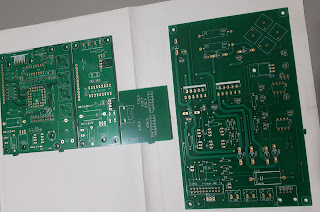
I put some requests out via Moon.net for some controller PCB , for the Slew drive , i have a few replys


Zdenek - OK1DFC

Bill Booth VE3NXK

Walter ON4BCB


Ive ordered from Bill a set of boards, and also from Walter for the pcb with a programmed MCU.

 this is the slew drive ill be ordering a12inch version .


building the base .


starting the hole.

painted the large RSJ ready

 welded exta section to the bottom

 base now fixed in position , put 5 ton of concrete in there so very strong .

ill be building a tilt over section with a winch for easy access


This is the view looking due east for moon rise, the mountain at the highest point is about 7 deg when we acquire the moon , making it a bit tight for EME for GW to ZL.


new large array / dish mount.  got a few reply's , ordered in some PCB's so we can make a start with the controller interface part.


 MY QSL CARD ,  How i made my card from a flight video . we Have a big landmark here in Wales , its the two bridges that cross the Severn Es...