Wednesday 3 February 2021

 MY QSL CARD , 


How i made my card from a flight video .


we Have a big landmark here in Wales , its the two bridges that cross the Severn Estuary .


i grabbed a frame from the video to produce my QSL card.


I have been experimenting with UAV and remote flying for a number of years , done some world record on distances , this fligt was over an hour and covers over 25 miles , It was an autonomous  filming the video ih hi res.

https://www.dropbox.com/s/66n960oosiaq38s/2nd%20crossing%20fast%20edit%20.mp4?dl=0


have a look at the video


 Problems with the W6PQL 70 CM 1KW amp.


The amp that I built has developed a problem on one of the LDMOS devices,


this has resulted in one of the device failing .

After inspection I found the case of the device had been chipped , so not sure if something dropped on it to cause it to then fail.


After trying to power it up have the Magic smoke off the device , confirming it was a gonner for sure.

problem with these device when we built it , the device is flow soldered onto the heat spreader, so it will all have to be removed and de soldered without affection the other good device .


After looking around i found  another pallet LDMOS from Italab


This is a 1kw Pallet , running off 50v at around 40 amps , si i may well just remove the problem amp in my Cased unit and fit one of these instead.


Sunday 31 January 2021

 Converting the FT847 to a more stable Frequency with GPSDO


As it is still giving drift even with the Crystal heater module.


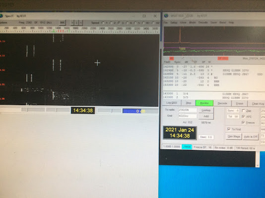
you can see the rapid drift here on the signals due to the oscillator drifting like crazy.


I was on the Moon and one station mentioned i had drift , i noticed this when powering on the FT847 , which requires time to heat up the crystal.

but still the drift was to high even  after warmed up ,


I found a Radio ham that could supply a module to fit the FT847 , this then accepts a 10 MHz input and then applies 22.625 MHz to the oscillator circuit 


here is the modification requirements kindly provided by PA0BAT

I have reproduced it here , correcting some errors .


Xtal MODIFICATION FOR YEASU FT847with 10 MHz Ref

This Modification Instruction briefly describes how to install a DF9NP made oscillator (see Fig. 1) into a Yeasu FT847 transceiver.


Fig. 2 shows where the Oscillator Board will be placed.


PROCEDURE:

  1. Remove top cover and bottom cover of the transceiver, and remove the protection plate with loudspeaker.

  2. On the component side of the Oscillator Board are a number of pins.
    Cut the upper half of the pins, to prevent that they later get in contact to the top cover of the transceiver.

  3. Prepare a distance keeper for the Oscillator Board. It will be placed underneath the Board.

    This can be done as follows (see Fig. 3):
    Take a piece of cardboard, thickness about 1.5 mm. Cut three pieces in the size of the Oscillator Board. Then cut holes in it, corresponding to the protuberances at the rear side of the Board.
    Stack the three card board pieces and glue them together, to form a 4.5 mm thick distance keeper.

    Fig. 3 Distance keeper of card board


4. Install an SMA female connector (or an SMA F/F feed-through) into the vent slot at the rear of the transceiver as shown in Fig. 4.

REAR VIEW 


TOP VIEW

Fig. 4 Installing SMA connector or feed-through

  1. Turn the transceiver upside down. Remove the large PCB. Do not forget to label the electrical connections and/or to make pictures, in order to put it all together later again.

  2. Locate the reference quartz XT1001, small trimmer TC1001 next to it, and small capacitor C1109 (at soldering side of PCB). See Fig. 5 and Fig. 6.

Fig. 5 Location of XT1001 and TC1001 


3

Fig. 6 Principle diagram of reference oscillator

  1. Remove XT1001, TC1001 and C1109 from the PCB.

  2. Via a ceramic capacitor (22 pF or so) the signal from the new Oscillator Board is applied to the base of Q1034.
    Solder a ceramic capacitor to the correct soldering hole of XT1001 (see Fig. 7).

    Fig. 7 Placing ceramic capacitor and connect coaxial cable 


4

9. Replace the large PCB.

10.Scratch away some lacquer to get access to the earth plane. This is to connect the shielding of the coaxial cable to the Oscillator Board (see Fig. 7).
Connect the coaxial cable and lead the other end to the installation position of the Oscillator Board.

11.Take a length of wire and solder it to the point shown in Fig. 8.
This is the DC supply for the Oscillator Board.
Lead the other end of the wire to the installation position of the Oscillator Board.

Fig. 8 DC supply point 


Now the Oscillator Board is to be placed. It is kept in position by three pieces of wire, which are soldered to surrounding coil housings.

12.Take the Oscillator Board, and solder three pieces of wire to its earth leads as shown in Fig. 9.

Fig. 9 Soldering wire pieces to Oscillator Board 


5

13.Bring the Oscillator Board in its position. Put the carbon board distance keeper underneath.

Solder the three wire pieces to surrounding coil housings (see Fig. 10).

Fig. 10 Position and attaching the Oscillator Board

14.Connect the two coaxial cables and the supply wire to the Oscillator Board (see Fig. 11).

Fig. 11 Oscillator Board placed and wiring connected 


6

15.Apply and/or replace tie wraps where applicable.

16.Check that the Oscillator Board does not touch the cover plate with loudspeaker, when that is placed.
For safety/insulation, a piece of carbon board or other suitable material could be glued to the underside of the plate.

17.Apply cover plate with loudspeaker, bottom cover and top cover. Ready we are! 


__________________________________


after carrying out this mod , here are some images .


 Afer all the work done i had problems getting this to work,


I got an accurate freq counter and measured the output from the board , it did show the 22.6250 MHz initially but still we had no functioning radio , no sound , no S meter readings .


 A calibrated freq counter do 10 milli hertz


 comparing the 10 MHz to a rubidium standard


This was a puzzle ?. i removed the connection to the input at the base of the transistor and re installed the crystal , things then came back to normal , so we haven't killed anything .....


I had purchased the Leo Bodnar SPSDO and this was going to be used to inject the 10 MHz locked signal to the board, after checking the board again i found the freq was anything but 22.6250 MHZ at the oiutput.


so i ended up removing the board altogether , and since the leo Bodnar GPSDO can go up to 800MHz , i programmed it with the USB interface and the provided software supplied , then checked it on the Counter , SPOT ON,  the levels were to high so i inserted a 6 dB SMA attenuator in the line and feed the output direct to the Crystal oscillator transistor via a 22pf capacitor , also set the output on the interface to 12MA as it was adjustable, with the attenuator and levels set this was we had a decent drive the the FT847.

put everything back together and VIOLA all working !! .

Later in the week i had some of the big guns check me off the moon , rock solid now !!!.

so if you thinking of getting a stable lock with e FT847 or any other radio i would recomemnd the Leo Bodnar interface and a simple attenuator and blocking capacitor , simple and easy.


 here is me working a station you can see the strait signals , unlike before


here are two station working , you can see the clear traces , dead strait traces now.


Sunday 15 November 2020

 I worked an EME VK station in very heavy rain


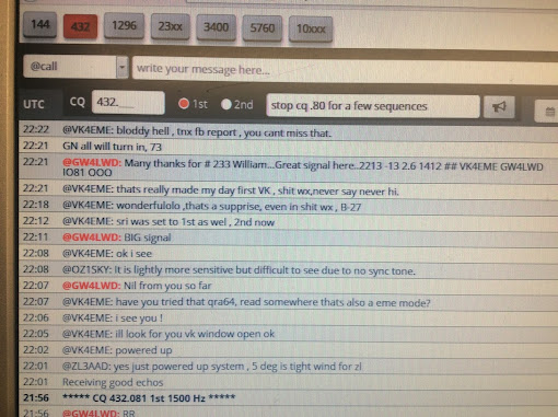
During October , when we had very heavy rain ,I could see a VK station on the Moon.net logger , the moon was just rising in the East just above the terrain .

after chatting i said i would see if we could receive him , it was very heavy rain at the time . I did not

expect anything .  what a surprise he was very strong even though we had heavy rain at the time , that's a surprise , we worked no problems and even got a good signal report in VK land at-13

                         Here is the chat on the logger .

                                                            and the actual qso in JT65B


 I worked my first USA station on EME.


 What a signal ! , this is him calling CQ a few weeks later . 

one of the biggest signals on 70cm eme , compaired to DL7APV and HB9Q.


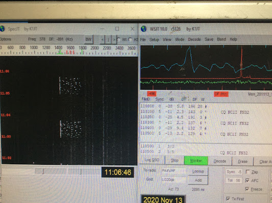
                   here you can see the signals ,  decoded and the signal levels.

                   in the recording above the signals reached -9db !.


this is a screenshot of the actual qso in jt65B


Saturday 24 October 2020

 I purchased a 2 meter pallet from OK1DFC Zdenek, 

it's a 1KW LDMOS on a pallet , so I initially fitted it to a large heat sink for testing .


This module is capable of a KW on 2 meters, i tested it with just below 2 watts input to take it to full power . Since I've fitted it into the main amp and purchased a low pass filter , this way was share the PSU, meters etc rather than another cased unit .

still having problems with the main Meanwell psu tripping , it a pain and would trip mid QSO, still no idea why its doing this , i resorted to building another backup PSU using ex server power supplies , connecting te in series to give 50vols at 44 amps.

normally we cant connect the power units together as the negative rail on these is connected to the ground of the case of the unit , this would give a short on the other power units and it would not work.

I found a simple mode was to take out the PCB , the one corner screw grounded the negative rail to earth  so i isolated this , , earth now is just that , not connected to the Negative rail.

I run the amp off this and made some qso, even this amp trips when PTT is pressed , so something is pissing them off as they are quite sensitive . They do reset  , unlike the Meanwell main PSU that i can not use , for a £500 psu its not good.

this is them running the Amp.

Building this power supply was a good learning curve , each unit cost only £12 on ebay , but you take your chances as sometimes you get duff units , i got 8 of them and two proved duff. Against the cost of the meanwell unit its a no brainer .


We have to modify each unit to isolate the earth from the Negative rail on each power supply which is very easy to do, since we are connectiong them in seires we cant have the negative rails connected to the case of each unit .


 Finding the FT847 is drifting , got a kit to make it more stable .

 , it's a heater unit that fits on the crystal.


moved the LPF filter in the amp to the top for easy access after it was blowing caps

the FT847 is a bloody good LNA killer I've killer two LNA's , whats happening it puts out a hi power pulse on PTT , the then get to the output side of the LNA as ists switched in to receive, then it blows the saw filter.


Solution is two fold ,i could fit the inhibit mod on the atu. but best of all is to use separate TX and RX lines , there is easy access to the rx input inside the FT847 , so got it coming out on a n SMA connector to the LNA,   Now the RF path goes to the Amp only , on receive the LNA is switched in . I've  added a sequencer from VHF Design as the W6PQL sequencer give problems, it just enables the bias on TX and manages the temperature of the LDMOS devices now, it inhibits tx of the Heatsink get to warm.

luckily my FT847 had a SDR module , but no good for VHF, its HF only.


 MY QSL CARD ,  How i made my card from a flight video . we Have a big landmark here in Wales , its the two bridges that cross the Severn Es...